Introduction
This library has been created to remove the non constant thickness effect of a cylinder sample placed in our neutron (works also for X-ray) beam. For such sample, the transmission signal will be much higher on the edge compare to the center of the sample. Post analysis of such sample is then very challenging. This library creates a new image corresponding to a sample of constant thickness. Thickness being the diameter of the original sample.
Principle
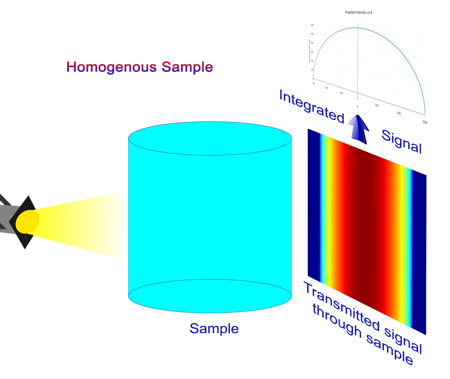
Any homogeneous cylindrical sample placed in a beam (neutron for example) will show a much higher transmission signal near the edge seen by the beam, compare to the center. This is simply due to the fact that the beam has to go through more material at the center compare to the side.
ATTENTION This library only works with cylinder placed in the vertical position!
The following figure illustrate the experimental set up and the signal measure for an homogeneous and inhomogeneous sample
In order to correctly analyze data for those samples, one must cancel this cylindrical effect by “making” the sample flat related to the direction of the beam.
The user needs to specify the position of the center as well as the radius of the cylinder. The program will then produce an image corresponding to the same sample as if it was rectangular.
Such samples are called homogeneous because they are made of only one uniform and homogeneous material.
But program also work with inhomogeneous sample for which the cylinder is hollow such as shown here.
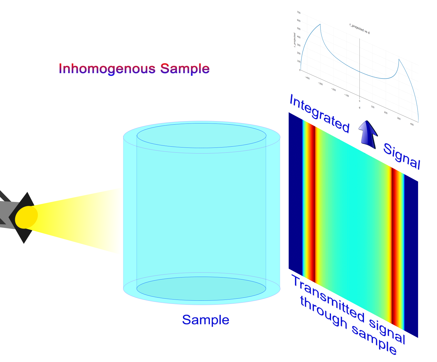
Program works the same way, user needs to specify center, inner and outer radius of material sample.
In order to run, the program only requires the user to define
the center of the cylinder(s)
the radius(dii) of the cylinder(s)
Attention
The correction implemented here is a linear chord-length division: it flattens inputs that are proportional to the neutron path length (attenuation maps, −ln(T), thickness-calibrated data). It is not the Beer-Lambert (exponential) correction required for raw transmission data — that derivation lives in Cylindrical Geometry Correction for Transmission Data and its implementation is tracked in issue #57.
Algorithm
Homogeneous Cylinder
Let’s consider a solid cylinder of radius \(R\) centered on the vertical axis, with the beam direction perpendicular to it.
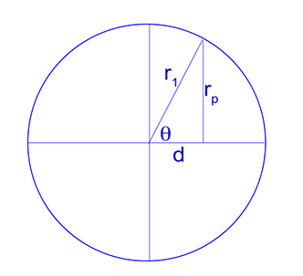
At horizontal offset \(x\) from the center, the chord length the beam traverses through the cylinder is
and the correction factor scales each pixel by the ratio of the center thickness to the local chord length, \(2R / r_p(x)\). The exact behavior — including the value 1 at the center, NaN at the tangent edges \(|x| = R\) (zero chord length), and 0 outside the cylinder — is documented on the implementing method, rendered here directly from the source so it cannot drift:
- static GeometryCorrection.homogeneous_correction(x: float = 0, radius: float = nan) float
Calculate correction factor for solid cylinders.
Parameters
- xfloat, optional
Horizontal position relative to cylinder center. Default is 0.
- radiusfloat
Cylinder radius.
Returns
- float
Correction factor for solid cylinder at position x: 0 outside the cylinder (
|x| > radius), NaN at the tangent edges (|x| == radius, zero chord length), finite inside.
Inhomogeneous (Hollow) Cylinder
For a hollow cylinder with outer radius \(R_\text{out}\) and inner radius \(R_\text{in}\) (the API calls these Radius 1 and Radius 2 respectively, and always stores the larger value as the outer radius), the chord length has three regimes: through both walls and the bore (\(|x| < R_\text{in}\)), through the solid wall section (\(R_\text{in} \le |x| < R_\text{out}\)), and outside the cylinder.
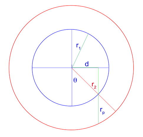
The correction normalizes by the center thickness \(2(R_\text{out} - R_\text{in})\):
- static GeometryCorrection.inhomogeneous_correction(x: float = 0, inner_radius: float = nan, outer_radius: float = nan) float
Calculate correction factor for hollow cylinders.
Parameters
- xfloat, optional
Horizontal position relative to cylinder center. Default is 0.
- inner_radiusfloat
Inner radius of hollow cylinder.
- outer_radiusfloat
Outer radius of hollow cylinder.
Returns
- float
Correction factor for hollow cylinder at position x.
Output geometry
The corrected image of each input has shape
(height, 2*outer_radius - 1): the cylinder region spans the columns
\(x \in [-R, R]\) and the two edge columns \(x = \pm R\) are
trimmed, because the chord length vanishes there and the correction is
undefined.